Sunday, May 3, 2020

Soliton JR Installed with water cooling in the Ghia with Warp 9 Motor

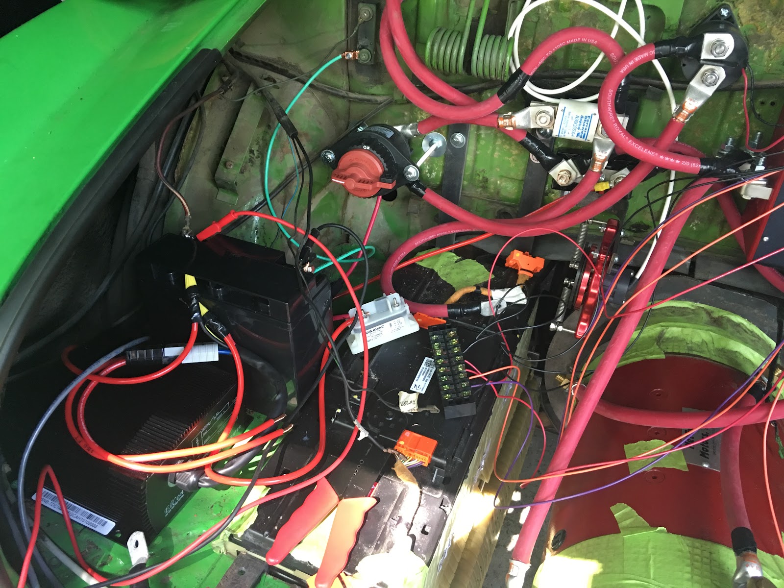
The Synkromotive controller was having problems so I replaced it with a Soliton JR. The Soliton needs liquid cooling so I bought a transmission cooler and a PC liquid cooling kit. Everything connected together without any problems. I filled the reservoir with antifreeze and distilled water and it works fine!


Here is the final installation. I may need to add a fan to the radiator if it overheats on the highway, this is not really a highway car so probably won't be a problem.
Soliton JR installed on the firewall in place of the Synkromotive


Adapted a PC Liquid Cooling Kit which includes a reservoir and 12 volt pump. This installed nicely next to the controller.


Transmission radiator installed behind the passenger side rear wheel next to the batteries

Problems with Synkromotive DC 750 Controller


Synkromotive DC750

I have been driving the electric Ghia for 2 years without trouble. Recently, after fully charging, the Synkromotive controller would not activate the main contactor.

It showed an over voltage error. I was charged to 200 volts, however, it read 218 volts which was over its factory programmed upper limit. I tried to reset the factory voltage calibration to fix the problem, however, i could not access the administrator settings and the company is no longer in business. So on to plan B - buy a different controller. I settled on the Soliton JR which i picked up used for $900. It lists for $1,899 at EVwest.
Evnetics Soliton Jr.
Soliton JR
The main thing I do not like about the Soliton is that it needs liquid cooling to perform properly. The Synkromotive was air cooled. Setting up a liquid cooling kit with radiator and pump adds weight and complexity. It is also bigger and heavier than the Synkromotive. On the plus side, there are more of them out there and it is easier to find replacement parts and get them repaired. The Soliton also does not need an external contactor so I can remove the one that was installed for the Synkromotive.
netgain controls electric vehicle throttle cable
Netgain Cable Pull Hall Effect Throttle

I had a problem hooking up the Netgain cable pull throttle because I forgot the proper wiring instructions. I couldn't figure out green, white, and blue wires.

I eventually stumbled across the info:


The functions of each wire on the wiring harness are the following:


Orange: 0.8V to 4.45V, signal 1

Blue: ground for signal 1

White: 5V supply for signal 1

Green: 1.6V to 4.95V, signal 2

Black: ground for signal 2

Red: 5V supply for signal 2

Drain wire: grounded


Once I hooked it up properly, I was able to calibrate the throttle and ot worked fine.


Tuesday, September 5, 2017

Karmann Ghia EV Conversion - Battery Balancer/Equalizer instead of BMS, Bad Chevy Volt cell


There is new technology available to balance batteries which is very simple, modular, and powerful. I have experience with BMS systems that can only balance at the top (when fully charged) and can only balance batteries that are almost perfectly in sync. When using some older batteries and newer batteries together in one pack, these type of balancers do not function as intended and in my experience do not fully charge the pack. They try to burn off some current from the high cells but can't keep the voltage from tripping the high limit which shuts off charging for a minute. It then turns back on and the same thing happens. It never charges the stronger cells that sit at a lower voltage. Typical BMS systems can only burn off 0.5 Amps per cell to top balance. This is wasted energy and heats up the batteries. The new battery balancer moves energy from one battery to another continuously and can move up to 10 Amps per cell. This is obviously a more powerful and flexible solution.
Additionally, you no longer need a 12v accessory battery, you can just tap 4 of the lithium cells and they will not discharge to become out of sync, they will be continuously balanced with the rest of the pack.
Here is what the older style BMS cell balancers look like. They have an integrated resistor that can burn off 0.5 Amps from the batteries to try to balance them.
Elite Power Solutions cell balancers on GBS Lithium cells
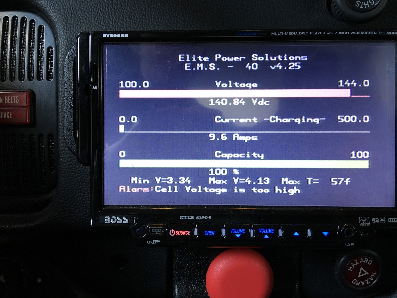
Here is an image showing the out of balance cells. The BMS was not capable of keeping the cells in balance.
Elite Power BMS display cells
This is what the 8s battery balancers look lime mounted in wood racks and wired together. I have six 8s units for my 48 cell battery pack.
Battery Balancers
These are made by Green New Energy or GNE, made in China. Website: http://www.gne2010.com/
Product link: http://www.gne2010.com/4s-8s-gne-active-battery-balancer-equalizer-bms-for-lithium-batteries
1s (one cell) unit available on ebay:

Multiple 1s units can be connected together for any size battery pack.
Here is my final arrangement, this can handle 48 cells.

Six 8s battery balancers connected to terminal strips

This shows the balance wires connected to the Chevy Volt Cells

Chevy Volt battery with balance connections
 After I hooked up all of the balancer connections, I found a problem One of my batteries had a bad cell.
2 kWh Chevy Volt Battery with bad cell
Here is a video showing how the bad cell was found. It showed no voltage and it was swollen.


Unfortunately I will have to buy some used 2 kWh Chevy Volt battery packs to replace the bad cell since one cell cannot be swapped out, the entire 12 cell module needs to be replaced.
Ebay: used 2 kWh battery packs

Tuesday, July 11, 2017

CAN communication with Chevy Volt BMS Battery Energy Control Module

As detailed in the previous post, I have a Chevy volt battery in the rear of the 74 Bug in parallel with the OEM BMS hooked up. I am trying to verify that the BMS is working. The BMS has a CAN communication system. The X1 connector on the BECM Pin 3 WH/BK is CAN- and pin 4 L-BU is CAN+.
USB CAN device

I bought an USB CAN communication device from eBay to read the CAN data. It is called: "USB-CAN USB to CAN bus Converter Adapter For professional Notebook PC Laptop" for $21.49. It is labeled USB-CAN A1+. It has the following features:

  • A standard CAN interface, CAN-H and CAN-L two-wire interface;
  • Jumper selectable access or disconnect the terminals 120 ohm resistance;
  • The USB interface supports USB2.0, compatible with USB1.1;
  • Supports standard and extended frames;
  • Support shielding / filtering;
  • Support two-way transmission, CAN send, CAN receiver;
  • High-speed CAN transceiver the TJA1050; baud rate between 20Kbps-1Mbps optional;
  • USB interface directly powered, no external power supply;

Product link: USB-CAN USB to CAN bus Converter Adapter For professional Notebook PC Laptop

Software for Windows was available for download. It is in Chinese. The software is called "CAN bus debugging tools Ver 4.6". It detected the USB device on the appropriate COM port but I couldn't get it to read any data.

To be continued ...

Update:
I hooked it up and couldn't get it to work. Not sure if it is defective or if it is a software problem or if I hooked it up wrong.

Monday, June 19, 2017

DIY Tin Plating / Electroplating of Copper Bus Bars or Terminals

I was able to tin plate some of the bus bars and connectors for use in my electrical projects. Copper is an excellent conductor, however, copper connections are prone to oxidation and can become high resistance areas in the circuit over time, especially when exposed to the elements. This results in poor performance and possibly failure. Commercial products often use tin plated contacts and connectors to provide corrosion resistance. Tin is a cheap metal that maintains conductivity over time even when exposed to the elements. It covers and protects the copper. Gold plating or silver plating are other options which are more expensive.

Electroplating works by dipping the material to be plated in a solution and running electricity through the solution to move metal to coat the material. To tin plate copper, the positive terminal of the battery is connected to the tin and the negative is connected to the copper. The solution has tin dissolved in it. Sugar is added as a brightener.

Note: Caution must be taken when handling acid and when working with electricity. Wear protective equipment (such as gloves, goggles, respirator, etc. and use care in handling materials. Vapors may be harmful as well so avoid inhaling vapors and only work in an environment with good ventilation.

This is how I did it. Follow at your own risk.

Steps:

Materials: pure tin (ingot or solder), an acid, alligator leads, sugar, a battery, a non-conductive container, and the material to be plated - copper bus bar or connectors.


1. I dissolved some shavings of the tin in muriatic acid (hydrochloric acid). I only used 2 ounces of acid. I let it sit for an hour. It started bubbling immediately. The fumes smelled bad possibly toxic.
2. I added distilled water approx 5 parts to 1 part of the solution from previous step.
3. I Added some sugar to the solution as a brightener. I used about a tablespoon for a 2 cup glass.
4. I Attached the positive terminal of the battery to the tin and placed on one side of a glass container containing the solution. 2 D cell batteries connected is series makes 3 volts.
Positive terminal connected to tin ingot in solution
5. I Placed the copper bus bar into the container (not in contact with the tin). The part that is submerged was to be plated. The copper to be plated has to be perfectly clean - i scrubbed it with a scouring pad and washed with soap and water and avoided handling with my fingers to prevent skin oils.
6. Attached the negative terminal to the copper bus bar using alligator clip leads. Once this was connected, the circuit was complete and electroplating started and noticed bubbles.

7. After a couple of minutes, I removed the copper and rinsed it off. Then removed some scale from the plated area. Then plated the area a second time.


Here is the end result, tin plated bus bars
Links to sources of information:

http://transistor-man.com/electroplating_busbar.html
http://hackaday.com/2012/10/14/diy-tin-plating-for-bus-bars/
http://www.sharrettsplating.com/blog/the-tin-plating-process-a-step-by-step-guide/


Re-using Chevy Volt OEM BMS for EV Conversion

I decided to try to use the Chevy Volt BMS to manage the Chevy Volt battery pack used in the VW (Volkswagen) Beetle Electric Vehicle. Since all of the batteries are in one area, connecting the factory BMS harness was simple.
The entire Volt battery pack reconfigured into two rows fit into the area behind the rear seats of the VW. The original BMS units and wiring harness is easily connected. The batteries are strapped together.

The OEM BMS consists of a head unit (K16 Battery Energy Control Module - BECM) connected to multiple slave units (Battery Interface Control Modules - BICM) using the X2 connector, which are directly monitoring the voltage and temperature of the batteries. The units communicate with each other over a CAN network. There is an inductive current sensor and some contractors also connected to the system. The head unit (BECM) controls the balancing functionality and communicates with the vehicle over a separate high speed CAN network on the X1 connector.

A copy of the Chevy Volt Service Manual (PDF) is needed to understand the wiring connections. Here is a link to a thread about the manual. Other copies could be found with an internet search for "2012 Chevrolet Volt Opel Ampera Service Manual".
This is where the BECM is found. It is where the battery control center is and where it is connected to the automobile systems. This needs to be disassembled to remove the BECM.

BMS harness connection X2 to K16 BECM. 
BECM unit K16. The port on the left is X2 connecting to the BMS wiring harness. The port on the right is X1 is connected to power through red and orange and ground through black as shown.

The head unit (K16 BECM) is supplied with 12 volt vehicle power (X1 connector pin 2 RD) and an ignition-on 12 volt signal (X1 connector pin 15 OG/YE).  Ground is connected to pin 1 BK Ground on the X1. It then turns on the slave units (BICM) by creating a regulated 5 volt signal (X2 connector pin 9 GY/RD). This is the bare minimum to turn on the system. The system should manage and balance the batteries as long as it is on. The problem is that I can't tell if it is working or what the status of the cells is without doing additional work to analyze the CAN communication data.

The X1 connector communicates with the vehicle. The CAN communication can be picked up from the X1 connector. On the X1 connector, Pin 3 WH/BK is CAN- and pin 4 L-BU is CAN+. I am hoping that I can analyze the CAN communications using a OBDII USB interface. There are many threads that use Arduino to access/analyze the data. This thread is very informative: http://www.diyelectriccar.com/forums/showthread.php/attempting-hack-chevy-volt-drivetrain-107946.html .

Updates:
Bought USB CAN converter from eBay but couldn't read data.
USB-CAN USB to CAN bus receiver Converter Adapter For professional Notebook PC

Friday, June 16, 2017

New Project - 1974 VW Beetle previously converted to electric vehicle

NEW PROJECT - 1974 Volkswagen Beetle
I was looking through eBay for electric vehicle conversions and first I came across a 911 cabriolet. I bid but didn't win. Then I found a 1974 VW Beetle in Albuquerque, NM which had been converted. It had high end components with a lithium ion battery pack with BMS, a Elcon charger and a Kostov 10" motor. I bought the car and had it shipped to NJ.

Unfortunately, things were not functioning properly. The batteries were GBS 100 ah lithium iron phosphate. Half of them were half dead. I couldn't get them to charge to the same voltage. The pack sagged really badly when accelerating. I spent $1500 on new batteries and still wasn't happy because the cells wouldn't charge properly. The weaker cells would charge first and stop the charging process before everything was fully charged.
GBS Cells with sense boards in rear compartment
Elite Power Solutions BMS display
Elite Power Solutions BMS
I learned from this experience that it is much easier of all the cells are the same age and have the same characteristics. Too much difference causes the BMS to be unable to balance the cells. It is very difficult to keep adding cells and testing the system until it works properly. Also, these cells are bundled in groups of 4. Every time you change a cell, you have to undo the bundle and recompress them to get them to fit. The cells swell over time and often are not easy to get them back in. We bought a shop press to help squeeze the cells together.
Shop press squeezing GBS cells to fit in pack

After all that, my brother was using the car and forgot to disconnect the batteries and ran them down. The electronics were set up to constantly draw the main battery pack to keep the DC/DC converter on. This basically killed 1/2 of the batteries that were not replaced. This forced my hand. I was really unhappy with the performance of the GBS cells anyway. I decided to buy another Chevy volt battery pack and reconfigure the electronics. The Elite Power BMS is specific to the GBS cells and would have to be discarded. The charger also wouldn't work with the voltage of the Chevy volt pack so it also can't be used. Luckily the Soliton controller is rated for high voltage. Hopefully we can sell the good GBS cells and the Elcon charger to recoup some of the cost.
As far as BMS, I was hoping to re-use the OEM Chevy Volt BMS. The volt batteries would have to be cut down to fit in the area where the GBS cells were. My preferred configuration is to use the chevy volt pack in two halves paralleled together to make a 180 volt nominal 90 ah pack.
We found a 2015 pack from a salvage yard and had it shipped for $1650 total.
2015 Chevy Volt battery pack
Luckily the pack was good. All cells functioning properly and no damage. We went ahead and disassembled it. This is my second chevy volt pack so it took less than an hour.
Chevy volt cells taken out of the pack
We the proceeded to cut them down to rectangular shapes. This involved removing the side portions where the coolant normally circulates. This is dangerous and difficult. It is the only way to fit the cells in the space available. This has been done before, we researched. See project by Kraig Schultz.
Chevy volt cells cut on tablesaw
Once the sides are cut off, there is no way to fasten the cells together since the holes for the threaded rods are also removed. The cells need to be banded together with something. We bought Nifty Products SPSPKIT 252 Piece Polypropylene Portable Strapping Kit, 3000' Length x 1/2" Width Coil, Black from amazon.

We used 1/8"x5/8" copper bus bar to connect the two rows of battery cells together in parallel. I wanted to prevent corrosion of the contacts so I decided to electroplate the ends of the copper with tin. This is a surprisingly easy process. I first experimented with using electrical lead free solder as the metal. It worked but did not have the right finish. I then ordered pure tin ingot and tried again with a 3.6 volt battery and used some sugar as a brightener and no salt to limit current. This came out really nice.
First try electroplating with solder
Video of electroplating. You can see the metal coating the copper and bubbles of gas.
End result after scraping with a wire brush. Not optimal.

Bending and twisting copper bus bars with vice
Finished product before tinning
After electroplating tin plating, look at that shine!

To be continued ...

Thursday, February 9, 2017

Karmann Ghia EV Conversion - Voltmeter for main batteries

I decided not to use the Xantrex linkLITE which I originally purchased. The problem was with the voltage prescaler and the voltmeter. I ended up shorting it out a couple of times before I figured out how to properly isolate the 12 volt system. Also, the linkLITE cannot be calibrated and it is pretty expensive. The linkLITE only measures voltages up to 35 VDC so it cannot measure a high voltage battery directly. I also don't like the look of the Xantrex digital gauge in the dash. It does not match the other gauges. Instead, I decided to go with a voltmeter that can measure the full voltage of the batteries without a prescaler and that could also measure amperage off my existing shunt. The Xantrex came with a 500 amp 50 mV shunt which I already installed.
Here is a circuit diagram showing the isolated power supply, the voltmeter, current meter, low voltage, and high voltage systems:


I found a digital panel meter on eBay which measured high voltage and amperage simultaneously. The seller agreed to program it to work with my existing shunt. I mounted it under my dash with a bracket. It is not in the driver's line of sight, I have to look down to see it. This is fine for my purposes.

here is the eBay Item:
DC +/- 500A 200V Amp Volt Combo Meter Battery Monitor Charge Discharge Shunt DS

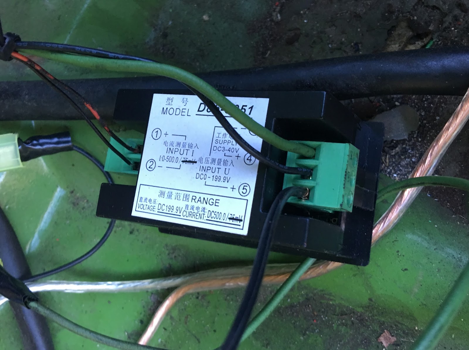
I hooked it up using a fuse on the high voltage side and with an isolating DC/DC converter to make sure that the high voltage and low voltage circuits remain isolated. VERY IMPORTANT!

Picture of back of panel meter


Links:
Isolated power supply: DC-DC Converter Isolated Power Module In 10-16V Out 12V DIY Favor
1/2 amp fuse: GOULD SHAWMUT ATM1/2 FUSE ATM 1/2 FUSE 600 VOLT 1/2 AMP
In line fuse holder: NEW LITTLEFUSE LEB-AA FUSE HOLDER 30AMP 600V: DIRECT EQUAL TO BUSSMANN HEB-AA

Karmann Ghia EV Conversion - Speed sensor problem / New gauges

I have come to the conclusion that I will not be able to get the WarP motor speed sensor kit to be compatible with the Synkromotive controller. There is a glitch that arbitrarily limits motor RPM to approximately 3600. The sensor seems to display RPM accurately.
Since I could not fix this problem, I decided to by a 52mm tachometer which will fit in the dashboard in place of the original clock. This will not prevent over-revving the motor but should give satisfactory feedback to the driver to avoid damage.

Tach from amazon

I installed it in the hole for the clock on the dash and it works nicely.

I ended up not liking the appearance of the amazon tach. Instead I bought matching gauges for RPM and Voltage from VDO. I like that the gauges match and they look similar to the original equipment. VDO makes the original gauges for the car. The other nice thing is the gauge light comes on with the headlights, not all the time, and it is attached to the main dimmer. It all works together nicely.


Sunday, November 27, 2016

Karmann Ghia EV Conversion - Ground Isolation

Proper Isolation of High Voltage System is CRITICAL!

I don't think there is enough information on how to isolate the 12 volt vehicle ground from the high voltage battery pack. When I set up the high voltage system, it was completely isolated from the vehicle electronics by design. The DC/DC converter is one area where the two systems interact, the model I used is an isolated model. The error I made was with the Xantrex battery monitor. It does not isolate the 12 volt negative from the high voltage negative and neither does the voltage prescaler that is required to measure voltages greater than 36 volts.
I figured this out the hard way when I mildly electrocuted myself by touching the chrome bumper with my body while touching the motor which had a residual charge with my arm. At that point I realized that there was a problem. If the systems are isolated, there will be virtually no voltage between the the voltage positive and the body of the vehicle (ground). I traced the problem to the battery monitor. As it turns out, there is an inexpensive and simple solution. It is an isolated DC/DC converter power supply which outputs 12 volts and 1 watt. I bought it on ebay for $6 from China. Unfortunately I had another incident where a tool I was using to secure the high voltage battery shorted to one of the battery leads from the vehicle chassis. This sent current through the battery monitor frying it.

Isolated power supply: DC-DC Converter Isolated Power Module In 10-16V Out 12V DIY Favor

 This type of isolated power supply is a MUST for your EV conversion. It improves the safety of the system and prevents damage to your 12 volt system by a short circuit. You should test your system with a voltmeter to make sure it is truly isolated. There should be no significant voltage when you test the high voltage battery positive and the vehicle ground with a voltmeter. If it reads a high voltage value, you should find the area where the systems are in continuity and isolate them properly.
While we are on the subject of safety, be sure to add as many fuses as you need. Any area where the high voltage system is connecting to something should be fused and the fused should be properly rated for the expected load. For example, the load to the controller may be 400 or 600 amps. The load to the DC/DC converter may be 15 amps and the load to the voltmeter may be 1/2 amp or less. You may also want to place fuses between the batteries especially if they are in separate areas of the vehicle.

Monday, August 1, 2016

Fixing mechanical problems with VW Karmann Ghia EV Conversion - in progress

I took the car out for a first run last week and noticed a few things that need attention.
1. Speed sensor/RPM problem\
2. The rear of the car is about 1.5" too low
3. The transmission is very difficult to shift, very sloppy

I will leave the speed sensor issue for a later post.

Its hard to say how much additional weight is on the rear. I took out the motor and exhaust system (approx $250 lbs) and added 240 lbs of batteries and a 150 lb motor in addition to wires and small electronic accessories (estimate 30 lbs). So I estimate that The rear is 160 lbs heavier than before. This weight compressed the suspension and it is now too low. I ordered Coil Over Shocks and will install them to try to bring the rear up to normal height.

With regards to the sloppy shifter, I read up and found that this is very common on old VW's. The shift rod connects the shifter up front to the transaxle in the rear. There is a shift rod bushing and a hanger up front which seems to wear and break frequently. There is also a shift coupler in the rear  which can also wear out. In my vehicle the bushing was destroyed but the coupler was intact.

Here is my coupler:
It looks pretty good.

This video shows the metal hitting metal from the destroyed bushing up front:


This is what a new bushing kit looks like on amazon:
Once it arrives i will install it and hopefully shifting will be a lot easier.

Friday, July 22, 2016

Preliminary Wiring plan and implementation Karmann Ghia EV Conversion

Before wiring everything together, I researched the proper circuit diagrams. I used the Synkromotive manual along with a diagram published by EV240Z here: http://ev240z.blogspot.com/2014/01/dc-battery-charging-through.html. I bought two screw terminal block strips with 8 positions each to connect the wires from the controller to the various components. The Synkromotive controller has 23 connections but they are not all used so 16 terminals should work.
Here is a page from the Synkromotive manual that I marked up. 

Here is a circuit diagram showing the connections to each of the 8 terminal blocks with numbers on the left side corresponding to the port number from the controller.

This circuit diagram shows the DC relay and 12 volt battery

This circuit diagram shows all of the major components.

I will need to locate some of the existing wires from the VW to connect to the terminal blocks. There is a continuous power line that runs to the ignition switch and there is a line coming back from the ignition switch when it is turned on. There is a relay wire which is powered when the key is turned to on. The chassis ground also needs to be connected. Other wires which need to be located are the reverse light and the brake light. I bought an enclosed DPST switch to activate the charging function.

Here is the front (Chevy Volt) battery. I drilled a 1.25" hole (with a 1.25" bimetal hole saw) where the right side steering column would go and tunneled the wires through. I used 1" Conduit Chase Nipples and locknuts to surround the wires as they pass through the sheet-metal. Once the wires are passed, I will reinstall the gas tank floor so that it can be used for storage or luggage.


Here is a work in progress view of the wiring of the Synkromotive controller to all of the contactors and the motor and other items. The battery and D/C converter are on the left side as is the wiring to/from the ignition key and existing car fuses. On the right side there are the charging contactors and 12 volt power supply for charging. The service disconnect switch is all the way on the left side. You can also see the battery cables pass through the firewall through a 1" Conduit Chase Nipple and 1" Locknut on the left upper corner. The battery terminals are covered in tape to prevent inadvertent contact and electrocution or shorting.

This view shows the area of the original car wiring, the 12 volt battery, the DC converter and transfer switch. Once all the connections are made and tested I will clean it up.