Here is a page from the Synkromotive manual that I marked up.

Here is a circuit diagram showing the connections to each of the 8 terminal blocks with numbers on the left side corresponding to the port number from the controller.


I will need to locate some of the existing wires from the VW to connect to the terminal blocks. There is a continuous power line that runs to the ignition switch and there is a line coming back from the ignition switch when it is turned on. There is a relay wire which is powered when the key is turned to on. The chassis ground also needs to be connected. Other wires which need to be located are the reverse light and the brake light. I bought an enclosed DPST switch to activate the charging function.
Here is the front (Chevy Volt) battery. I drilled a 1.25" hole (with a 1.25" bimetal hole saw) where the right side steering column would go and tunneled the wires through. I used 1" Conduit Chase Nipples and locknuts to surround the wires as they pass through the sheet-metal. Once the wires are passed, I will reinstall the gas tank floor so that it can be used for storage or luggage.


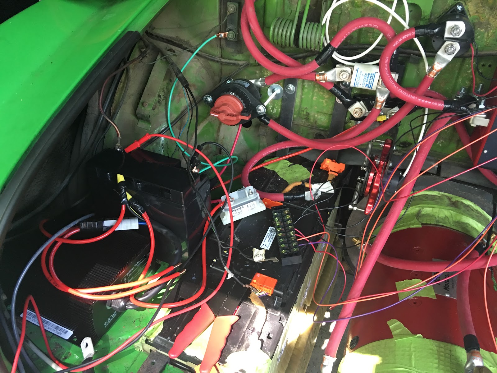
This view shows the area of the original car wiring, the 12 volt battery, the DC converter and transfer switch. Once all the connections are made and tested I will clean it up.


This circuit diagram shows the DC relay and 12 volt battery

This circuit diagram shows all of the major components.

I will need to locate some of the existing wires from the VW to connect to the terminal blocks. There is a continuous power line that runs to the ignition switch and there is a line coming back from the ignition switch when it is turned on. There is a relay wire which is powered when the key is turned to on. The chassis ground also needs to be connected. Other wires which need to be located are the reverse light and the brake light. I bought an enclosed DPST switch to activate the charging function.
Here is the front (Chevy Volt) battery. I drilled a 1.25" hole (with a 1.25" bimetal hole saw) where the right side steering column would go and tunneled the wires through. I used 1" Conduit Chase Nipples and locknuts to surround the wires as they pass through the sheet-metal. Once the wires are passed, I will reinstall the gas tank floor so that it can be used for storage or luggage.


Here is a work in progress view of the wiring of the Synkromotive controller to all of the contactors and the motor and other items. The battery and D/C converter are on the left side as is the wiring to/from the ignition key and existing car fuses. On the right side there are the charging contactors and 12 volt power supply for charging. The service disconnect switch is all the way on the left side. You can also see the battery cables pass through the firewall through a 1" Conduit Chase Nipple and 1" Locknut on the left upper corner. The battery terminals are covered in tape to prevent inadvertent contact and electrocution or shorting.

This view shows the area of the original car wiring, the 12 volt battery, the DC converter and transfer switch. Once all the connections are made and tested I will clean it up.
No comments:
Post a Comment